MMC Project

Support Files

AVR Kits

Projects using Atmel micros and BascomAVR
New projects  in development  Click Here

Users’ Section

Available

If you have any projects that you would like displayed, please send E-mail

Contact

E-mail for more information

Classified Section Items Available

The original PIC16F876 3.3volt Prototype

The original MMC 3.3v prototype Board

The MMC prototype using a PIC16F876 running on 3.3v. Parts used:

  • 16F876 28 pin mcu
  • Max233A for serial
  • An 24C65 I2C eeprom
  • LM2937 3.3 reg.
  • 10 Mhz xtal
  • Molex MMC socket
  • DB9 connector
  • Melabs’ Proto3 board
  • Misc: 4 caps, 6 res, pwr LED,reset switch and headers


The MMC is in a socket which is soldered to a small pcb. The small pcb has a 7 pin male header at the bottom which plugs into a female header on the prototype. This allows one to use the alternative connection shown below if an MMC socket is not available. The DB9 serial connector serves a dual purpose. It is used for data I/O to and also to program the 16F876 serially. A MAX233 (or equiv) was used instead of a MAX232 simply because it requires no external capacitors. In order for the 16F876 to operate at 3.3v its built-in brownout protection feature (BOR, PwrUpTimer) has to be disabled. The I2C eeprom is used as a temporary storage area. The SD/MMC writes data in blocks of 512 bytes, therefore it is not possible to write just one or two bytes at a time (does not apply to reading). Therefore one needs to store the data somewhere until it reaches a minimum of 512 bytes. Any I2C eeprom can be used as long as it can hold 512 bytes or more of data.

Prototype Schematic

Demo Code (PBP Ver 2.40)

Max233 Schematic

An alternative method of connecting the MMC if a socket is not available. is to use a female pcb edge-connector and a female header connector. This provides a nice snug fit for the MMC. A single row of pins are actually used since the MMC has contacts only on one side. Instead of using a ribbon cable and the female pcb header one could solder the edge connector directly to the prototype board.

Check the Workbench support area for available demo code

SD card proto pcb. for SD/MMC projects

Shown assembled (SD card not included)

MMSD9K $16.00

The SD card connections are configured for a standard SPI mode connection which is commonly used for interfacing with microcontrollers.

Ordering Page

A socket pcb for the SecureDigital (SD) card configured for the SPI mode. The kit includes the pcb and SD socket. The SPI connections are conveniently brought to standard spaced 0.1” header pads. Provisions are made for pull-up resistors on the data lines. SPI lines include MOSI, MISO, SCK and SS. The socket is backward compatible with MMC cards.

The new MMC/SD development kits

The modified MMC board which can use MMC as well as SD cards.

mmsd3fassm3w

MMSD3F Kit $59.00

Ordering Page

Assembly Manual

Shown assembled (SD card not included)

mmsd_loutw

MMSD3F pcb layout.

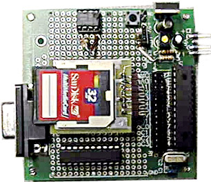
Same size as the MMC3 board except that it can be used with SD cards as well as MMC cards. The standard kit comes as shown below but without the SD card. It includes a PIC16F876, a Max233 (or equiv), an LM2937 3.3v regulator, SMD resistors, a 10Mhz resonator and a FM24CL64 FRAM plus the DB9 connector, SD and IC sockets, reset switch.

The smaller MMC/SD development kit.

Similar to the MMSD3F design but 25% smaller in size

Similar to the MMSD3 board but much more compact. It is a PIC based 3.3v development board that is interfaced to a SD/MMC socket. Serial I/O is available via a standard DB8F RS232 connector. The PIC can be loaded with a bootloader so that it can be programmed serially without having to remove it from the board. It also includes a 5 pin header for programming the PIC with a conventional programmer. The SPI lines from the MMC/SD are connected to the hardware SPI pins on the 16F876 / 18F252 PIC as are the serial RS232 lines. All of PORTA and PORTB pins are available for other purposes with the available pin outs. It includes a Ramtron 64kbit FRAM, a Max3232, SD/MMC socket, a 3.3v regulator, a PIC 16F876 or 18F252 and associated passive components.Requires a 7-16v DC supply

sdmm3fassmw1
SDMMF_layoutwjpg

Board layout

Shown assembled (flash card not included)

SDMM3F Kit $57.00

Ordering Page

Assembly manual

Please Note: This kit requires soldering surface mount parts (resistors,capacitors, IC3232 and FRAM chips. Working with SMD parts does require certain soldering skills

Source Code

Available experimental source code for reading/writing to a FAT16 formatted MMC. The code for the MMSD3F board and the SDMM3F board is the same. The code is written in PICBasicPro v2.47 from MELabs

PLEASE NOTE: The firmware is not a complete file system with . This would not be possible without a considerable amount of RAM to build large buffers. It only works with a single file in the root directory (no sub directories) and only FAT16 is supported. It is assumed that the user can modify and re-compile the code as needed for their own purposes. The code has been successfully tested with a variety of MMC and SD cards from several manufacturers. There are rare occasions when a card fails to be initialized.

Information: All PIC to MMC transactions must be in chunks of 512 bytes. Data to be stored is first saved to the external FRAM and is then automatically transferred to the MMC when 512 bytes accumulate. Storage is limited to a single file only, mainly due to the constraints of the PIC and available RAM. The code occupies almost 4k of programming space. As delivered, it demonstrates writing to a card by writing a 16kb ASCII text file to the card which can be read in the PC's card reader. Each time the code is executed the file is appended with 16kb more of text. The user can combine the source code in their own application by performing two steps. Bytes of data to be stored are sequentially assigned to a variable (E_BYTE) and then a subroutine (ESAVE) is called. Since the MMC/SD only writes in chunks of 512 bytes, the data is temporarily stored in the external eeprom. When 512 bytes have been accumulated the eeprom "buffer" is transferred to the MMC/SD card and the card's FAT and directory are updated at the same time. Since this transfer and updating consumes time, it makes it impossible to "stream" data to the MMC. Incoming data would have to be controlled by some means so that it pauses a few milliseconds every 512 bytes for the updated to complete. It is possible to use a PIC18LF2620 instead of the PIC16F876. The 18LF2620 has over 3k of RAM. This allows the creation of software buffers and increases the I/O rate considerably. Sample 18LF2620 code is also included. The original premise of the code was to implement it in long term data logging projects where data was received at a slow I/O rate. Using the demo source code one can modify/create their own applications.

SOIC8 to DIP8 Carrier

Useful tiny carrier! Use existing DIP8 sockets to try out new SOIC8 devices such as a FRAM to replace a standard eeprom. Available in the parts section ( includes mounting pins )

Shown with a FRAM mounted

All Rights Reserved, Copyright (c) COMPSys , 2007

Updated on:

April 22, 2008 

Windows is a registered trademark of Microsoft Corporation. PICMicro is a registered trademark of Microchip Inc.

AVR is a registered trademark of Atmel Corp., MAX is the trademark of Maxim Corporation